Thursday 19 November 2009

Work continues with Bridge board

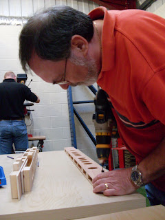
Over the last few weeks we have been building parts of the bridge board. It is a complex design and has taken longer to design than previously thought. There are 3 major features to the Board, a railway bridge, a road bridge and the river. They are all at different angles and gradients. These are a few photos to show the proportions of the design.


Sunday 18 October 2009

Track Alignment Vehicle

Diagram courtesy of Gauge O Guild
Following the instructions of the gauge O guild’s manual, we have built a Track Alignment Vehicle. This will help when laying the trackwork. It ensures we have laid the track correctly and there are no twists that may derail long fixed wheel vehicles

Friday 9 October 2009

Tentative attempts at signals

On our layout we are using BR(W) semaphore signals, the photo shows our first attempts at kit bashing a Model signal engineers kit.

Three way point

This photo shows the completed three way point, although on our layout the left hand road will never be used the point has been built to a good standard and would work if desired.

Second Point completed

This is the a 1 in 6 flat bottom point, it has had some weather applied to it as a test

Work starts on the Trackwork

This is a photo of the first piece of pointwork to be constructed, it is a double cross over made from Peco Individulay in flat bottom rail. On our layout we are having flat bottom on the main line and loop with bull head in the shunting yard and colliery line.

First efforts at the bridge board


After weeks of discussions and planning, we have begun work on the bridge board. It is a difficult board with different angles and gradients to be calculated. In the Photo there is one of the 2 webs made yesterday, these will support the river bed at the bottom of the board.

Friday 7 August 2009

Second shot of templates

This photo is taken from the other end of the layout, this is the colliery end with the colliery line on the right

First attempts with templates

This photo shows the templates laid out to show the rough track plan. We have now been able to check the lengths of the run rounds and ensure we have enough room as we hoped

The gradient on board 5

This is a photo attempting to show the different gradients on board 5, the mainline is the closer line dropping away to the left

Board 5 Completed

This photo show the completed board 5

Fitting the trackbed to Board 5

In this photo Richard and Dave are screwing 1 of the track beds to board 5, there are 2 levels on the board with the main line dropping away and the shunting yard remaining flat

20ft of layout

This is 5 boards of the layout fitted together, it is 20ft in length and these make up the major scenic boards. There is one other board to at the far end which is the bridge board and has to be specially made and 4 fiddle yard boards, 2 at each end

The gradient on board 4

This shot shows the gradient of board 4, the left hand track bed remains level. The right hand will be the main line falling away from the shunting yard.

Track bed fitted to board 4

This is a shot of the completed board 4, it is one of the simpler boards to fit the track bed on, but has a slight gradient at one end

Richard working hard

This is Richard putting the final screws in the outside frame for board 5

Screwing the main frame together

This is a photo of the framing being assembled, it shows Nick and Dave holding the framing down on the table to keep it square.

Countersinking the holes

This photo is of Richard countersinking the holes. We are taking full advantage of having a good quality pillar drill, it allows us to countersink with great ease and ensures every countersink is the correct depth

Construction of board 5 starts

This is a photo of Dave drilling pilot holes into the fames ready to be screwed together. We have 8 or 9 hole drilling jigs that allow us to mark the hole positions each time without having to do any calculations. This saves a lot of time.

Monday 27 July 2009

Board 5 pieces complete

In the photo you can see all 7 sandwiches pieces have been glued and are being weighted down by plate glass, this glass just happened to be in the warehouse at the time. It is very good for this task as it is a nice even weight across the sandwich length.

Building the Framing for board 5

This week we choose to work on the framing for board 5, Our progress this week included the marking and cutting of all of the lengths of Plywood and softwood. We could then cut mark out each sandwich piece for the hole drilling, once these holes were drilled we still had enough time to glue the sandwiches together. The photo shows Richard gluing the softwood to one side of the plywood.

Tuesday 21 July 2009

4th Board Framing complete

We have now finish the framing for the 4th board, which is now going towards the other end of the layout, it is fairly simple with a slight bit of gradient work on it.

colliery line

This is another picture to show the gradients on the layout, in this you can clearly see the steep incline of the colliery line.

Adding Gradients to a Layout

By changing the height of the track bed risers you can put in gradients, in this picture the track bed at the back is the colliery line which is steeply inclined up to the colliery, the line at the front is the main line which slopes back down towards what would be the bottom of the valley

Boards 2 and 3 completed

After starting with the simplest board, which was the middle of the layout, we have now worked our way towards the colliery end of the layout. This shows the next 2 boards completed. This picture doesn’t show the gradients very well.

Board 1 completed

This photo shows Richard and Dave holding the first board. this is the underside of the first board shortly after completing it, this shows all 7 different sandwich pieces that are used for each board. This photo shows 2 people lifting the board, but it is very easy to lift on your own.

Fitting the track bed

After the framing was completed we could then cut out a piece of 9mm plywood to act as the track bed, this was the glued and screwed to the rises to give it a firm base.

Main construction

This is a shot of Richard and John building the first board, we are adding the first web that goes across the board and adds support for the track bed. In this shot the main fame for the board is already put together, it is important when screwing this together, that the frame is dead square

Screwing it together

All of the sandwiches have now to be screwed together to reinforce the glue, it is worth making a note of where the main construction screws are going, as you need to leave some space for these

Weighing it down

In this shot you can see us weighing the sandwich down while the glue goes off, it is important to ensure it stays dead flat at all times while gluing. To the left are other sandwiches we have made, all have gone though this process and will be used in making the first board. Nick, who runs a computer firm, would like me to ensure to any of his customers, these are old hard drives and aren't going to be fitted into their new PC

Gluing the second layer

This is a shot of us adding the second layer to the sandwich

Monday 20 July 2009

Mistakes are to be learnt from

This is a shot of myself holding up the first mistake we (John) made, correct one is on the left. Please note the position of the hole on the right one is too low.

More shots of Board 1


This is a shot of Richard and Dave gluing the risers onto the plywood while Dave ensures they are flush to the edges.

More work on first Board

Work is continuing on the first board, is this picture 1’’ by 3’’ blocks of softwood are being stuck to the plywood with another layer to be stuck on the outside, this will make the sandwich construction. These softwood blocks are the risers that the track bead will sit on.

Work commences

This is a picture of David sanding back the holes on our first bits of plywood.
The holes save a little bit of weight but allow the wiring to go down the layout
This is a basic diagram of the track plan and layout of buildings and structures